
BOLT Lifesaver Technical Introduction
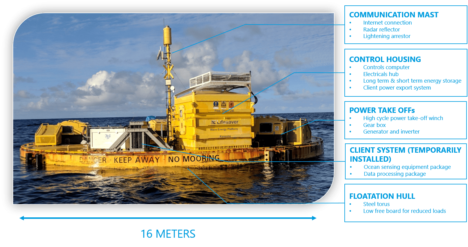
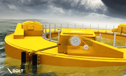
Developed and build from 2010 to 2012, BOLT Lifesaver (from the Lifering shape of the hull) is the latest and largest embodiment of the Fred. Olsen BOLT class of point absorber wave energy converters.
BOLT Lifesaver was developed by the Fred. Olsen team of engineers and detail designed and manufactured by UK engineering company Supacat Ltd. Completion was done at A&P Falmouth March 2012. Following her two years of deployment at FabTest off the coast of Falmouth UK, she was refurbished, modified and shipped in her individual modules to Hawaii, where she was reassembled and installed at the US Navy wave energy test site in March 2016.
| System Parameters | |
| Nominal sea state | Hs 2,75m, Ts 6,5s |
| Avg. power output in nominal sea state | 30kW (3 PTOs, current config) 50kW (5 PTOs) |
| Total dry weight | 56 metric tones |
| Bill of material | $1.6M |
| Accumulated energy produced to date (July 2016) | 45MWh |
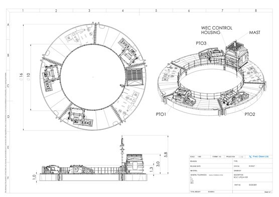
| Hull dimensions (outer dia. x inner dia. x height) | 16m x 10m x 1m |
Assembled of five hull sections, she can accommodate a total of five power take-off units, outputting a total of 50kW at the nominal wave state. However, only three PTOs have been built.
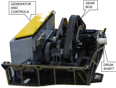
Power Take-Off Unit
The Power Take-Off Unit is the core of the Fred. Olsen wave energy conversion technology. Comprised of a high cycle winch, a belt drive gear box and an actively controlled generator, the PTO unit is generic, scalable and can be fitted to any floating structure to produce electrical power through damping of wave induced motion.
BOLT Lifesaver can accommodate five PTO units, though currently only three units are built and installed.
A PTO unit operates completely independently and obliviously of the other PTOs. This provides a redundancy for maintained operation in the case of a PTO failure.
Some key parameters for the PTO unit:
| Nominal sea state | Hs=2.75m, Ts=6.5s |
| Avg. electrical power output @ nominal sea state | 10kW |
| Generator nominal power rating | 84kW |
| Dry weight | 3.0 tones |
Key features of the PTO unit are:
- Fully electric
- Actively controlled mooring line tension through winch drum torque control
- High cycle winch line (several million cycles between service)
- Compensation for angles between winch line and winch drum arising to pitch/roll- and drift of the floating structure
- Compact and modular design
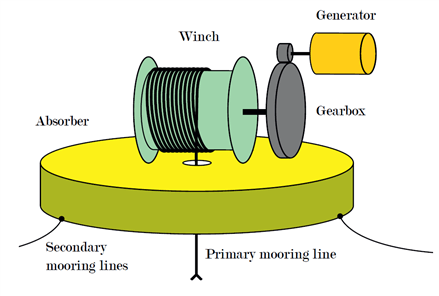
Winch
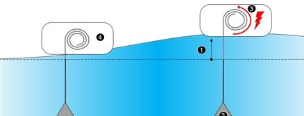
Energy is available from relative motion between the PTOs and the ocean floor. The component connecting these two reference points, is the PTO winch. The winch line is moored to the seabed at one end and wound around a drum at the other. As the PTO is displaced, the winch line is tensioned and inflicts a torque on the drum. Through a gear box, a generator provides a torque that results in a controlled winch line tension. As the PTO travels back down from a wave crest, the generator operates as a motor to wind the winch line back in with a controlled tension.
Horisontal drift as well as pitch and roll motion of the floating structure, gives rise to a constantly changing angle between winch line and drum. A guiding system helps compensate for this angle and ensures good alignment as the winch line is guided onto the drum.
Even the most sophisticated rope products that is exposed to bend under tension will see internal abrasion between strands and have a predictable lifetime of only a few hundred thousand bend cycles. Considering a typical wave site has around five million waves per year, Fred. Olsen found that a new winch line had to be developed in order for the technology to be viable.
Collaboration with a world leading manufacturer of transmission components, was initiated in 2010 to develop a winch line with increased capacity for bend over sheave load. Following six years of extensive rig- and in-sea testing, a patent pending winch has been developed with lifetime of several million bend cycles.
Gear box
Regular, off-the-shelf gear boxes requires routinely lubrication, are compact and inaccessible for maintenance and have poor resistance to offshore marine environment. In collaboration with Gates Corporation, a high ratio, belt based gear box has been developed that has low maintenance requirements, good accessibility for maintenance and high resistance to corrosion.
Generator control
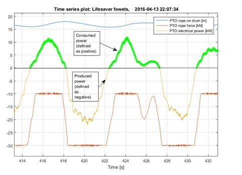
Absorbed energy is the winch line tension force multiplied by drum rotation. Hence, net energy is energy produced on upward motion minus energy spent winching line back in.
Generator, gear box, winch line and the floating structure makes up a complex system of dynamically couple masses.
This prompts the need for a carefully implemented generator control algorithm to extract maximal amount of energy while reducing system oscillations and force excitation.
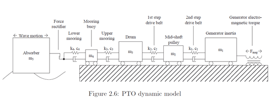
The generator control algorithm employed by the PTO unit is the result of extensive simulation and in-field parameter study. Velocity proportional damping and early force saturation has been a fundamental part of the Fred. Olsen generator control algorithm.
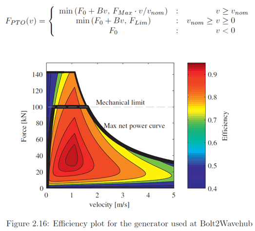
An expert of a production series with pull out tension 30kN (max. capacity 100kN per PTO), pull back tension 10kN (defined with negative signage) is provided below. Green graph is power consumed by PTO when winding back winch line, while yellow grap is produced power. Net delivered power is the sum of the two.
Detailed description of the Fred. Olsen WEC Power Take-Off development and design is found here:
Electrical Power System
Lifesaver has an advanced power system that allows for operating standardized industrial power equipment autonomously without grid connection, while still keeping the option of grid connection open.
Electrically, all PTOs are connected to a common DC-bus that serves as the backbone of the power system. This allows for natural power exchange between the PTOs and the power components, and ensures a natural balance in the power flow.
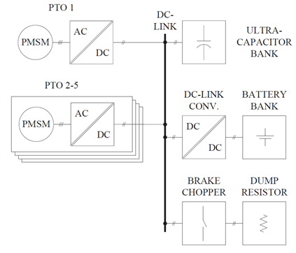
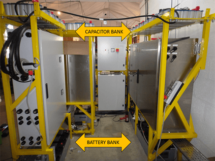
Available on the DC-buss is a short term energy storage comprised of a 1.1MJ (0,28kWh) ultra capacitor bank used to winch back the winch line in between waves.
A long term storage in the form of a 1470Ahr 24V battery bank ensures energy is available to keep the system alive during periods of calm seas.
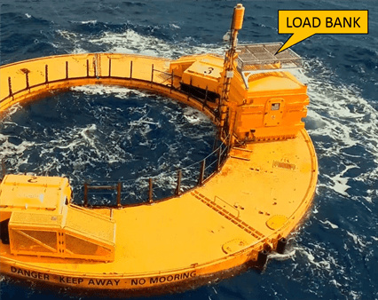
BOLT Lifesaver currently has no on-board energy consumer. The exported power is therefor dissipated in a load bank of electrical heat resistors on-board.
Hull
The hull provides the buoyancy force that the PTO winches can pull against.
The BOLT Lifesaver hull has the shape of a square profile torus. With inner diameter 10m, outer diameter 16m and 1m height, the total available buoyancy is 1200kN. Subtracting the 550kN gravitational force of Lifesaver, the PTOs have a total of 650kN buoyancy force available for production.
| Volume | 121 m^3 |
| Dry weight | 35 tones |
| Bill of material | $714k |

To allow for welding and rough handling, and because she is one-off, it was decided to build the hull out of steel plates. The design is stiff and rigid and accommodates along side mooring of a variety of vessel sizes.
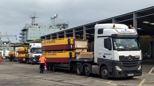
Comprised of five identical sections, the hull is transportable by road and ship.
Control & Monitoring
The operational principle of BOLT Lifesaver autonomous operation. System settings are determined by the operational team and fetched by the control system over internet with certain intervals.
Autonomous operation
A number of on-board auxiliary systems such as cameras, pumps, fans etc. consumes a certain amount of the produced power. The control algorithm constantly evaluates the sea state to assess whether conditions are sufficient for net surplus production. The lower sea state for surplus operation is denoted cut-off sea state.
Control algorithms
The primary operational objective is to optimize system up time and reliability. This involves close monitoring of state of components relative to lifetime expectancy and maintenance planning.
Second to this is quality of power production. The wave resource on any given offshore site is constantly fluctuating, while a consumer would request a certain minimum power level to be continuously supplied. The most challenging situation is operation in low sea states close to surplus cut-off level. Much effort has been put in by the engineering team to tweak control of generator and auxiliary systems to reduce cut-off sea state. The availability of energy from on-board energy storage also enables continuation of operation through shorter periods of below cut-off sea states.
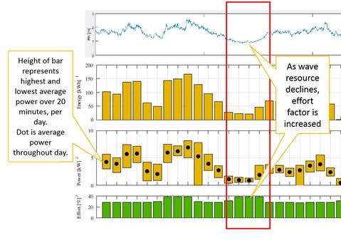
Effort factor
PTO efficiency is a complex function of wave height, wave period and generator control. A parameter called the “Effort Factor” is developed that expresses how hard the PTOs are working to extract energy from the waves. The lower the wave resource, the higher the “effort factor”.
Software
A proprietary control and monitoring software has been developed by the engineering team, based on the LabView software platform from National Instruments.
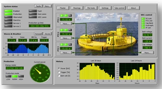
Monitoring and data recording
Software and an network of IP cameras allow for live monitoring of operation.
Additionally, data acquisition systems are installed that logs data from a number of sensors and instruments on board and provides the engineering team with invaluable operational information for post processing and analysis.
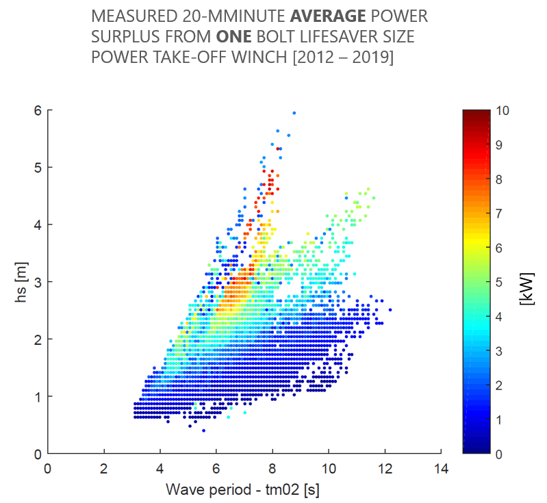
Performance
Power performance data from more than 30.000 hours of operation is presented in the below plot. Each point represent the average power surplus over a 20 minute time series, meaning that peak powers going through the drive train is typically 20-25 times this number.
Simulation results of exportable electrical power of various scales of the current PTO design at two different sea states and single/multi PTO setup, are illustrated below. “System diameter” along x-axis assumes a buoyant cylinder onto which a Fred. Olsen PTO unit is installed. Though the results indicate an increased available power production up to 1000kW, Fred. Olsen believes a single system beyond 500kW is not viable.


